A fire sprinkler system is an active fire protection method, consisting of a water supply system providing adequate pressure and flowrate to a water distribution piping system, to which fire sprinklers are connected. Although initially used only in factories and large commercial buildings, systems for homes and small buildings are now available at a cost-effective price. Fire sprinkler systems are generally designed as a life saving system, but are not necessarily designed to protect the building.
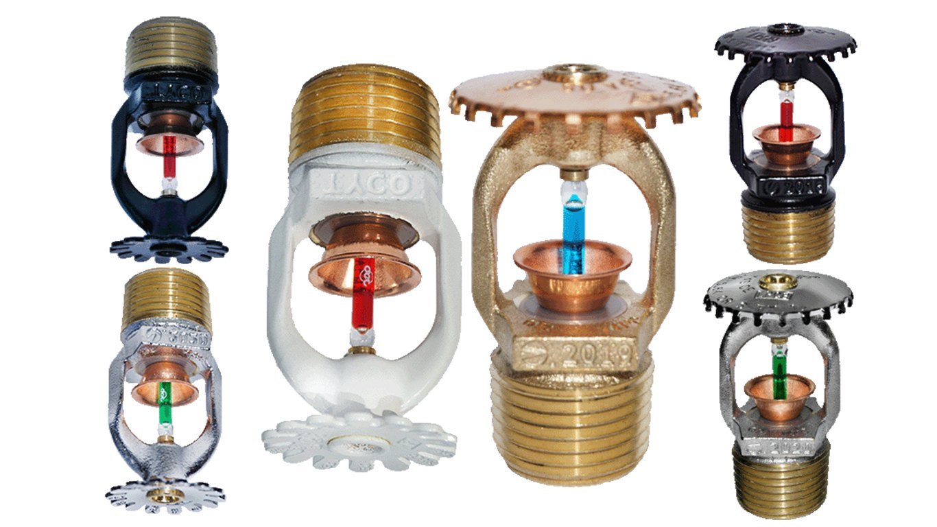
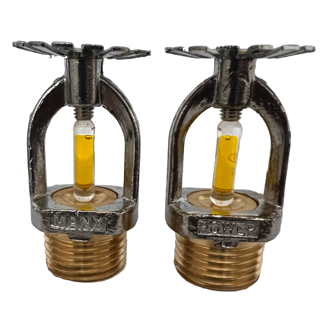
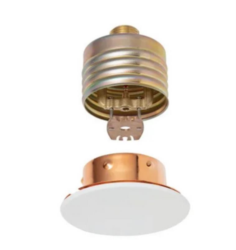
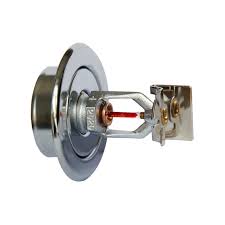
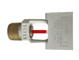
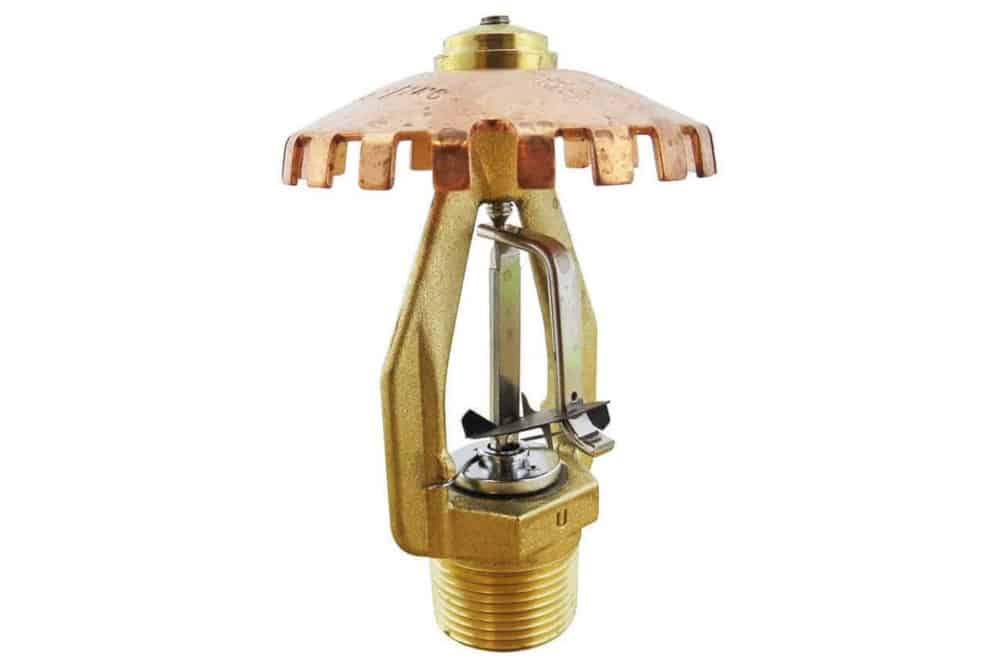
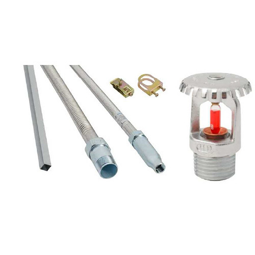
An Automatic Fire Sprinkler System is designed to contain and control an unfriendly fire allowing your family the precious time needed to escape from danger and decrease the amount of damage to your valuables from heat and smoke. An Automatic Fire Sprinkler System is a network of water-filled pipes which starts at your domestic water service line and ends with strategically spaced fire sprinkler heads located throughout your home. The sprinkler heads are frangible bulbs filled with a liquid that, when heated, expand causing the bulb(s) to break and the system to release water. The water from the sprinkler head will cover the area where the fire is located and will continue to operate until the fire department can fully extinguish the fire.
Over the years, fire sprinklers have become mandatory safety equipment in most parts of India, in certain occupancies like newly constructed hospitals, schools, hotels and other public buildings, Industries, etc. subject to the local building codes and enforcement.
Sprinklers may be required to be installed to reduce potential property losses or business interruption. Each sprinkler activates independently when the predetermined heat level is reached. Because of this, the number of sprinklers that operate is limited to only those near the fire, thereby maximizing the available water pressure over the point of fire origin.
Fire Sprinkler Systems have been the biggest breakthrough in fire protection in the last 100 years. Fire sprinklers are the most effective method of protecting lives and property. Sprinkler systems are now recognized as being so effective they are being made mandatory in many situations.
Every building should be classified for fire risk under the following categories: light hazard, ordinary hazard group and high hazard group. Factors involved in classifying a building's hazard level include the material used in construction, the occupancy level, the materials stored in the building, the processes performed in the building (and whether these processes include flammable liquids), ceiling heights, ease of egress, and the amount of floors and rooms.
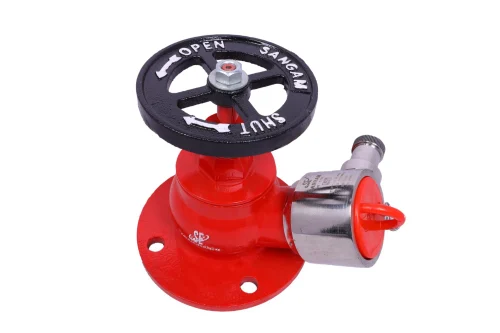
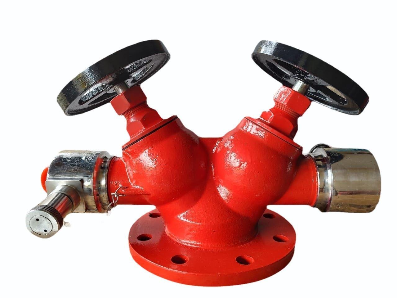
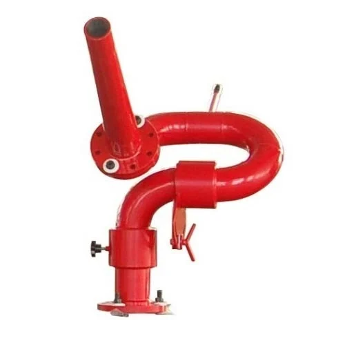
Being one of the oldest but yet the most effective and common fire fighting solution, a well designed and a well laid out Hydrant System forms the backbone of the entire fire fighting system. It comprises of heavy duty above & underground piping with accessories. External and Fire Escape Hydrant valves are provided at every strategic location. A fire hydrant is a pipe that allows water to flow from a water main with the control of a valve in order to put out a fire.
Fire Hydrant Protection System is designed to fight fire of huge proportions, in all classes of risks. It is designed to be in operation even if a part of the affected structure collapses.
Dry barrel and wet barrel are the two kinds of Fire Hydrants. The wet barrel fire hydrant holds a constant water supply, while the dry barrel fire hydrant needs to have a valve release to let water in.
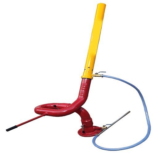
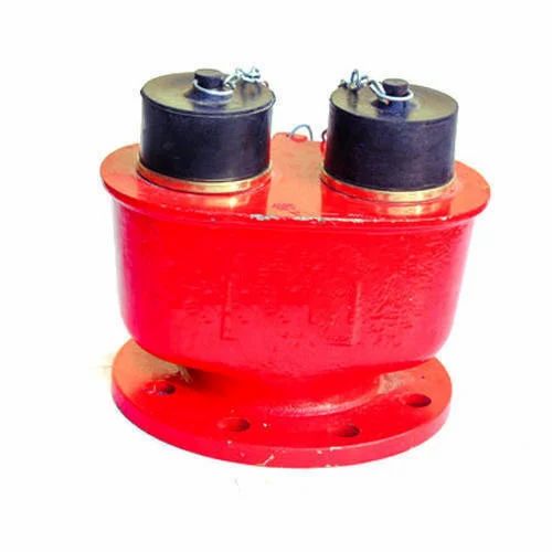
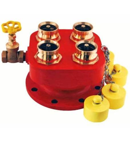
It is designed to provide rapid access to water in the event that a fire breaks out. Fire Brigade Connections are installed as standalone systems which act like building-specific fire hydrants, providing fire protection which will be readily available to fire fighters.
Guidelines and approval for Hydrant System are available from various national and international organizations like: NBC, NFPA, TAC, IS, FM and Local Fire Authorities.
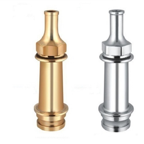
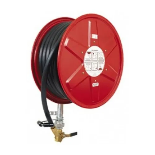
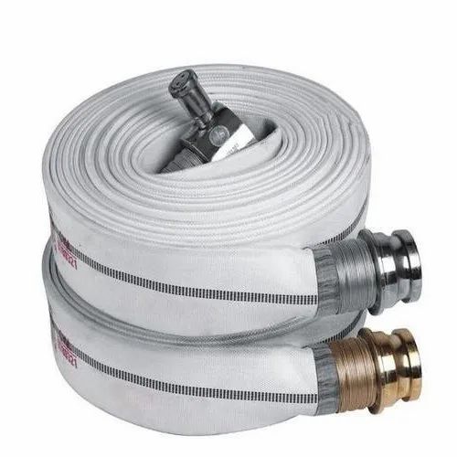
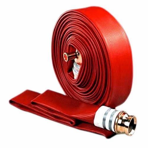
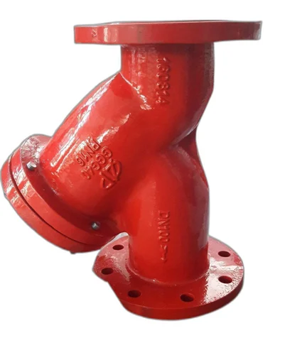
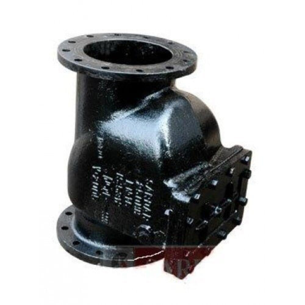
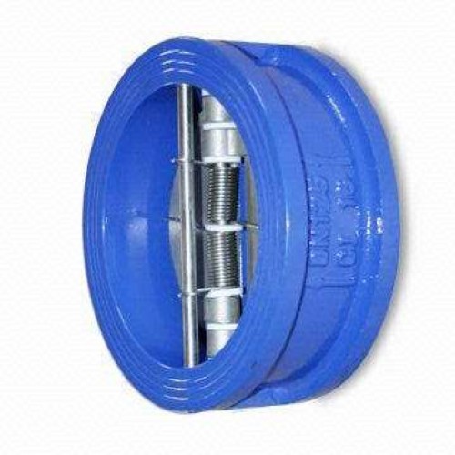
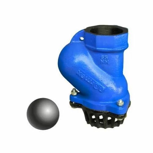
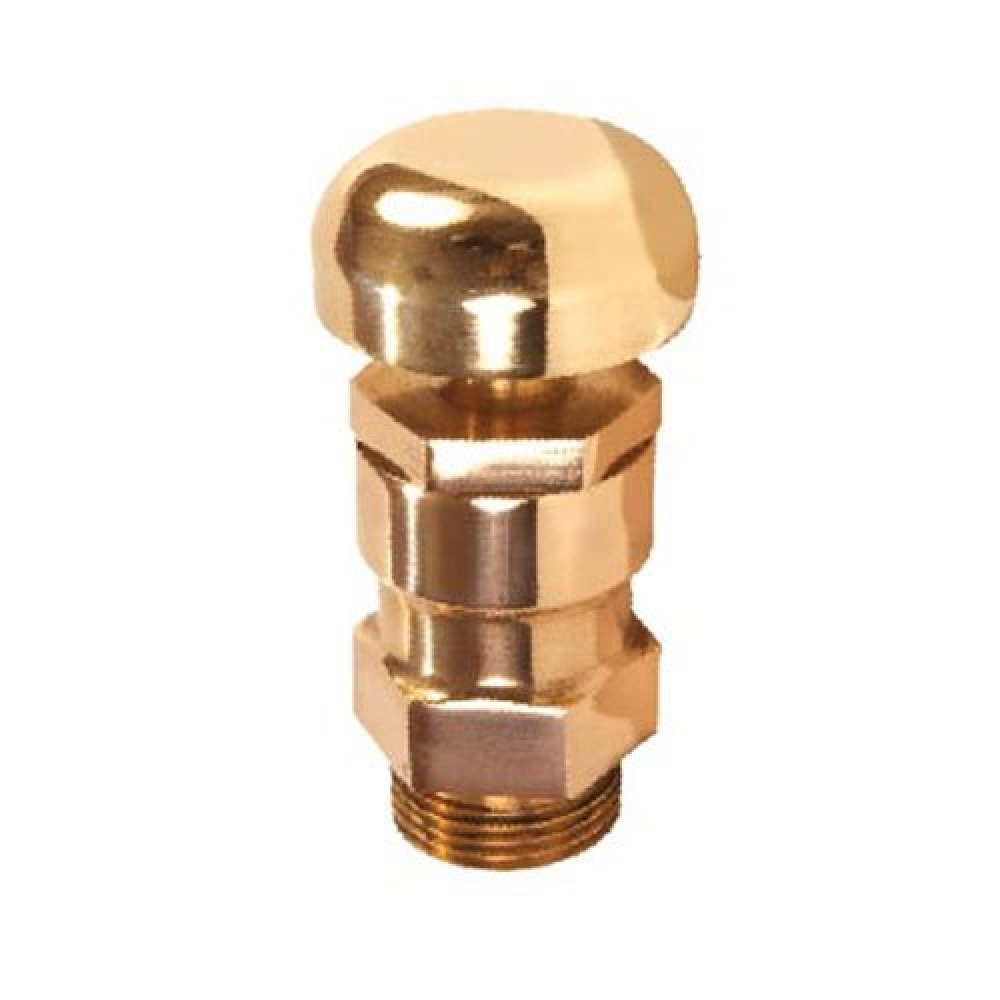
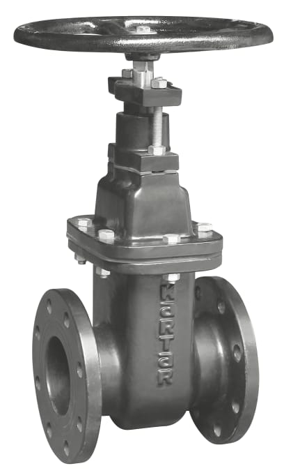
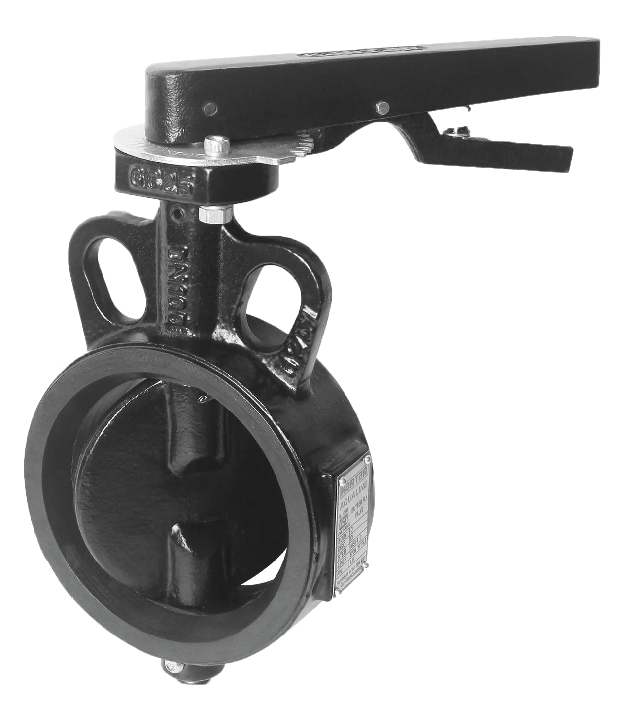
Fire Fighting Pumps & Accessories:- • Piping • Panels • Landing Valves • Hoses • Couplings • Hose Reel • Branch Pipes & Nozzles • Fire Brigade Connections • Wiring & Instrumentations • Maintenance Valves
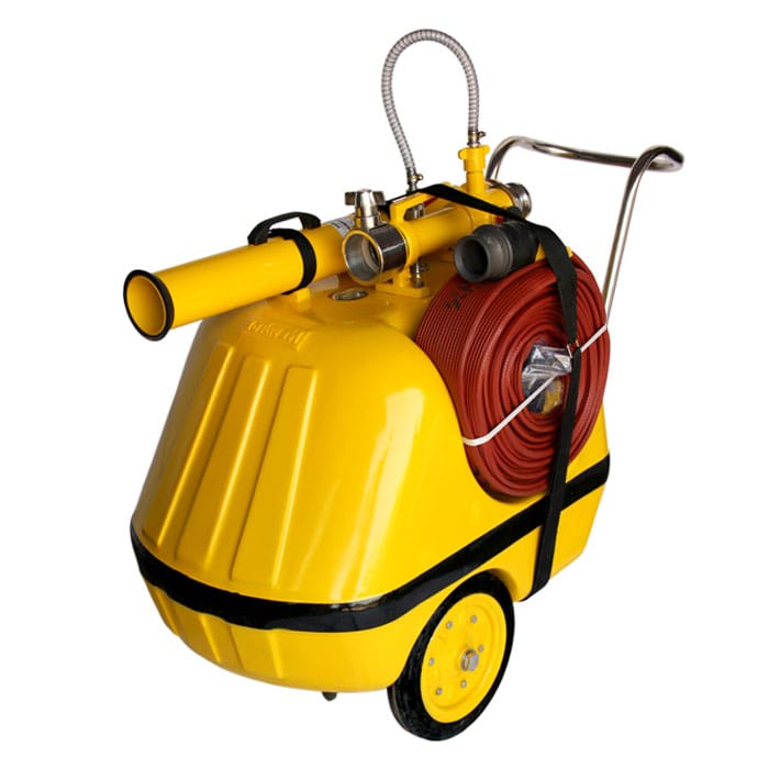
Fire hydrant installation consists of a system of pipe work connected directly to the water supply main to provide water to each and every hydrant outlet and is intended to provide water for the firemen to fight a fire. The water is discharged into the fire engine form which it is then pumped and sprayed over fire. Where the water supply is not reliable or inadequate, hydrant pumps should be provided to pressurize the fire mains.
A typical hydrant installation fed directly from water main and pressurized by fire pumps is shown as below:
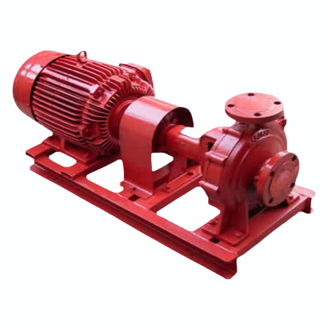
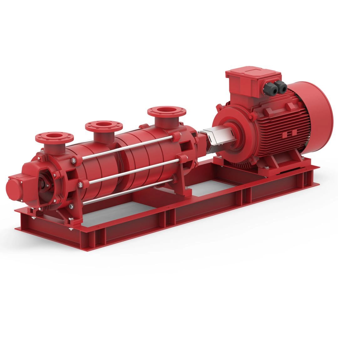
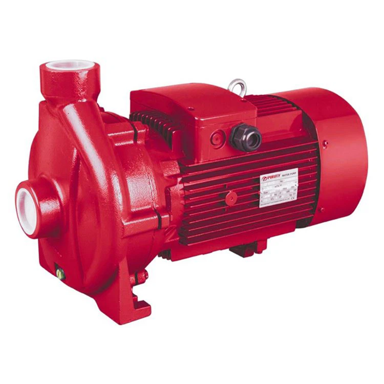
The Fire Pump Station comprises of the Jockey Pump, Electric Driven Pump and Stand-by Diesel driven Pump. The pump operation is automatic through pressure switch contacts based on header Pressure in the hydrant network. The delivery of the jockey ump and main pump is connected to the common delivery header.
The Fire Hydrant Line is always kept pressurized with water. In the event of any minor pressure drop in the system, the pressure reaches the preset pressure setting for Jockey pump, the Jockey pump will start automatically to compensate the pressure differential. In the event of opening one or more hydrant valve for fighting fire the Jockey pump will not be able to make up this water loss resulting in further pressure drop. When the falling pressure reaches the Preset pressure for main pump, the main pump will start automatically. In case of electric supply failure, stand by diesel engine driven pump will come into operation.
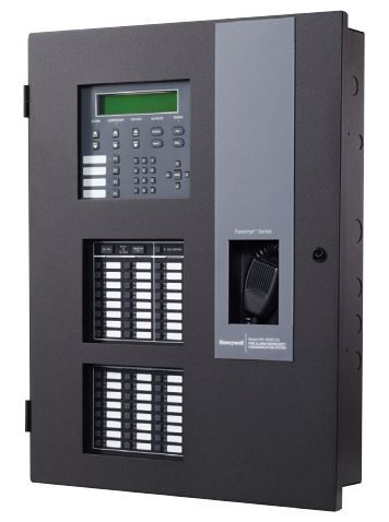
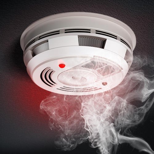
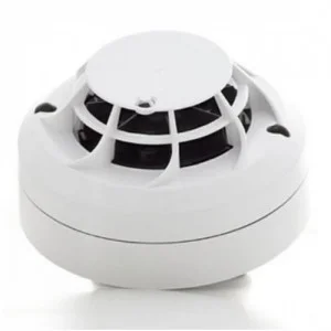
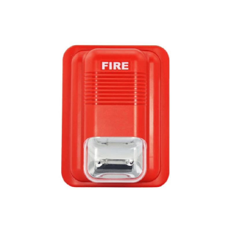
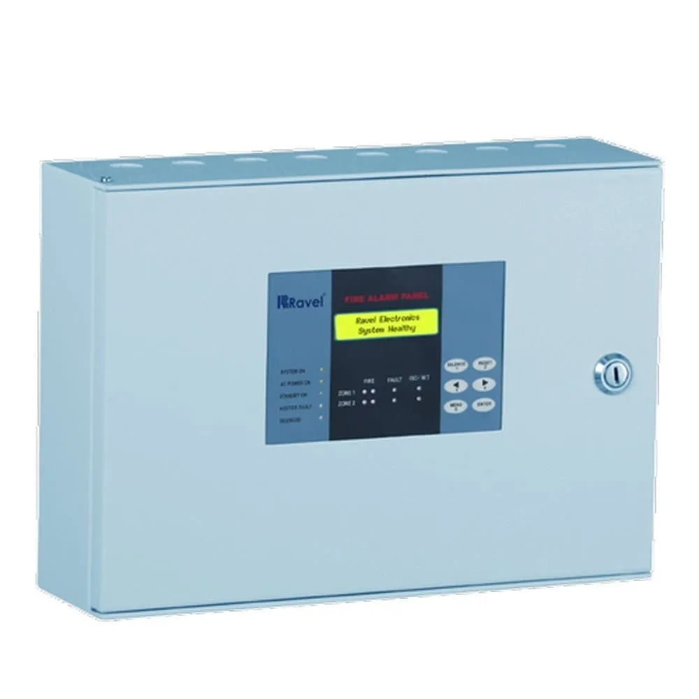
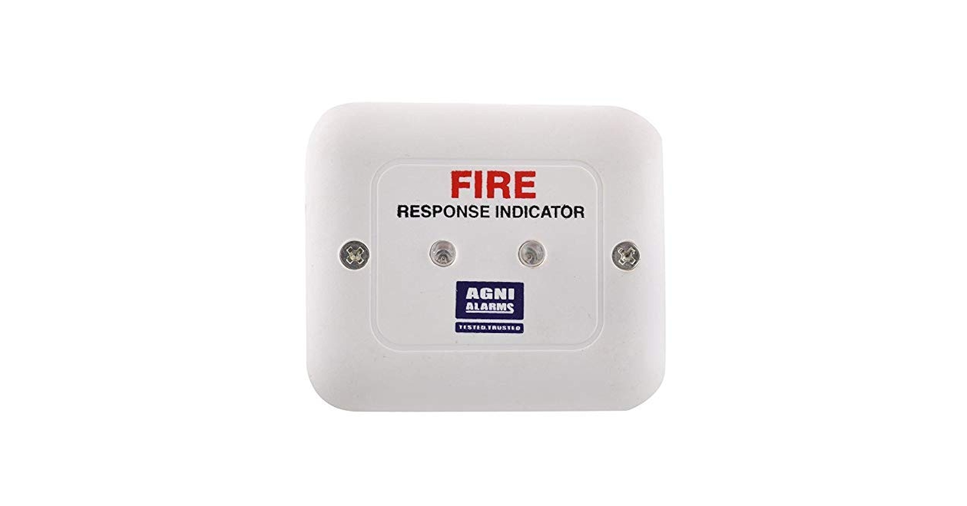
A Fire Alarm Control Panel (FACP) / Fire Alarm Control Unit (FACU), is an electric panel that is the controlling component of a fire alarm system which is installed at various places as a protective measure against fire; sounds an alarm when actuated by a fire detection system. Fire Alarm System is essential to warn all occupants that a fire or emergency situation exists. Sometimes fire detection and alarm systems are used to compensate or to give special cover for items of high value. In case of fire early detection of smoke and heat helps in fighting the fire effectively & extinguishing it in nascent stage. Thus by early detection, we can prevent the fire from spreading in turn saving life and loss of property and business.
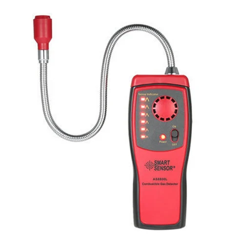
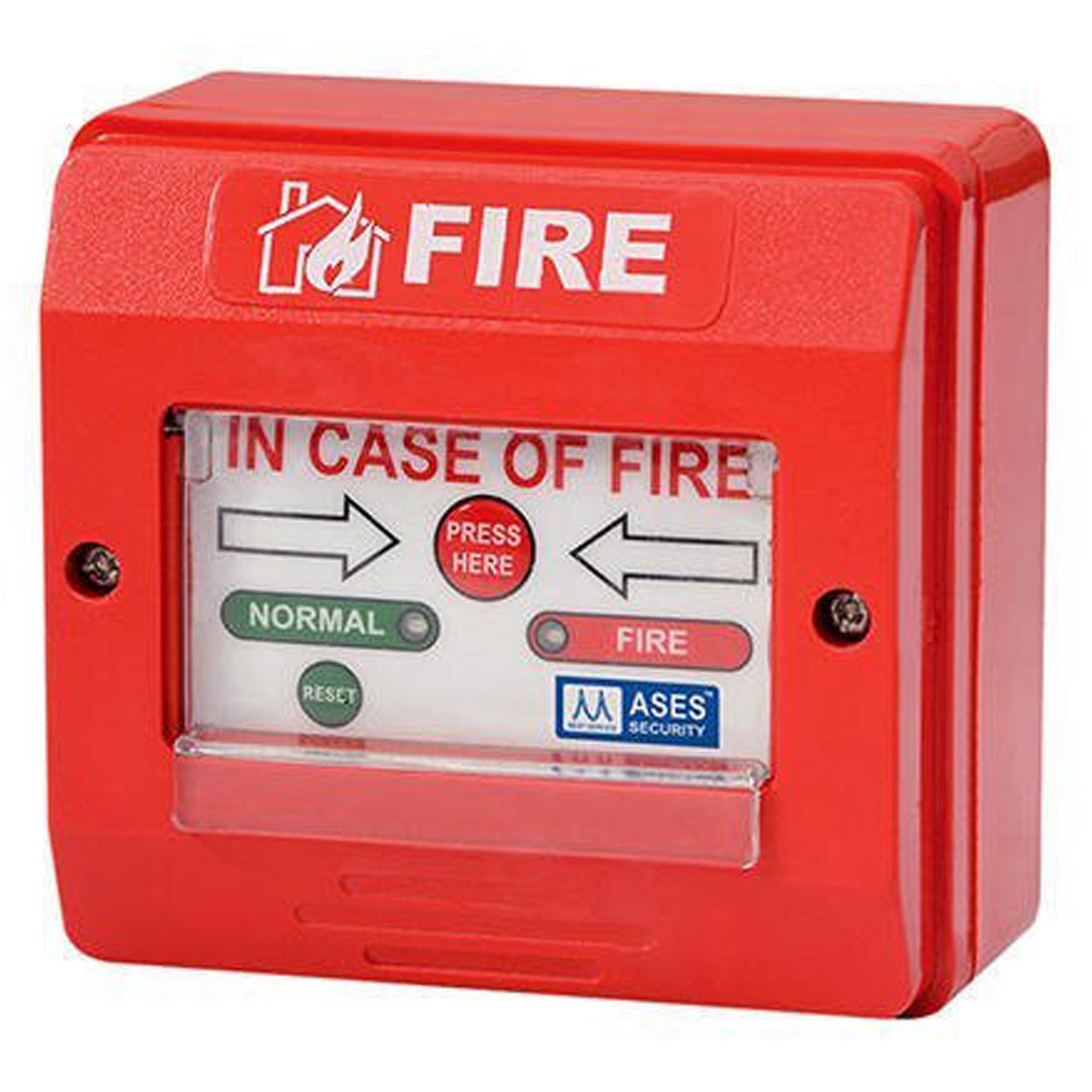
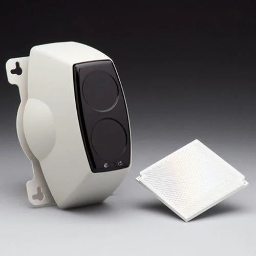
Whatever the reason, an automatic fire detection and alarm system generally provides a network of manual call points, fire sensors and alarm warning devices over the area covered. It is, in effect, the eyes and mouth of the building to constantly monitor the building and warn if a fire breaks out, or is suspected in the way we do, if we see flames or smell burning.
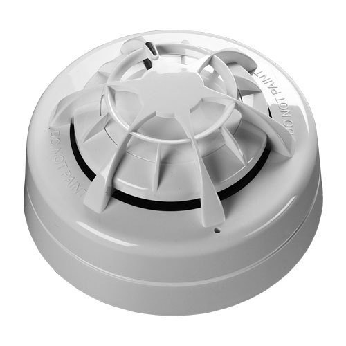
Analogue Addressable Fire Alarm Systems differ from conventional systems in a number of ways and certainly add more flexibility, intelligence, speed of identification and scope of control. For this reason Analogue Addressable Fire Alarm Systems are the natural choice for larger premises and more complex system requirements. These systems consist of a central control panel to which smoke alarms and heat detectors are connected, along with bells or horns that are activated when the system triggers an alarm. The control panel operates from house power but also usually contains an emergency battery which can operate the system for about 24 hours during a power outage. Addressable panels are usually much more advanced than their conventional counterparts, with a higher degree of programming flexibility and single point detection.
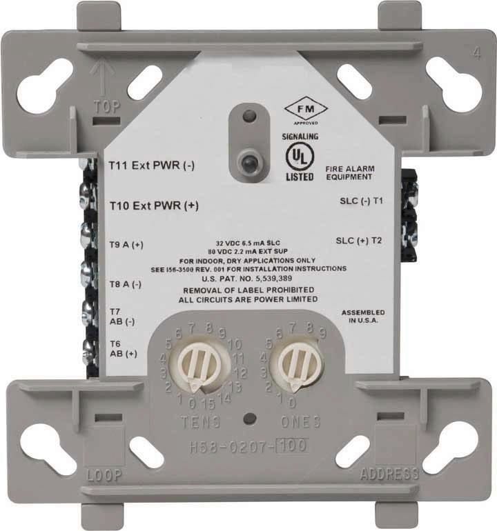
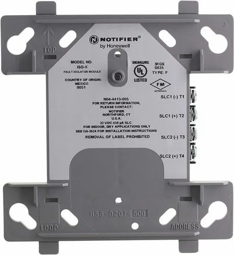
Panels usually have a number of signalling line circuit loops - usually referred to as loops. Depending on the protocol used, a loop can monitor and control several hundred devices.
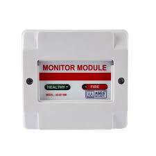
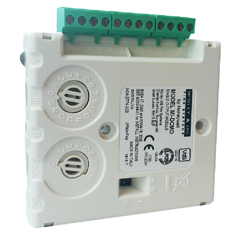
Each device on a SLC has its own address, and so the panel knows the state of each individual device connected to it. Common addressable input (initiating) devices include: Detectors, MCP’s, Warning System/Bell Relays, Activating fire suppression systems, etc.
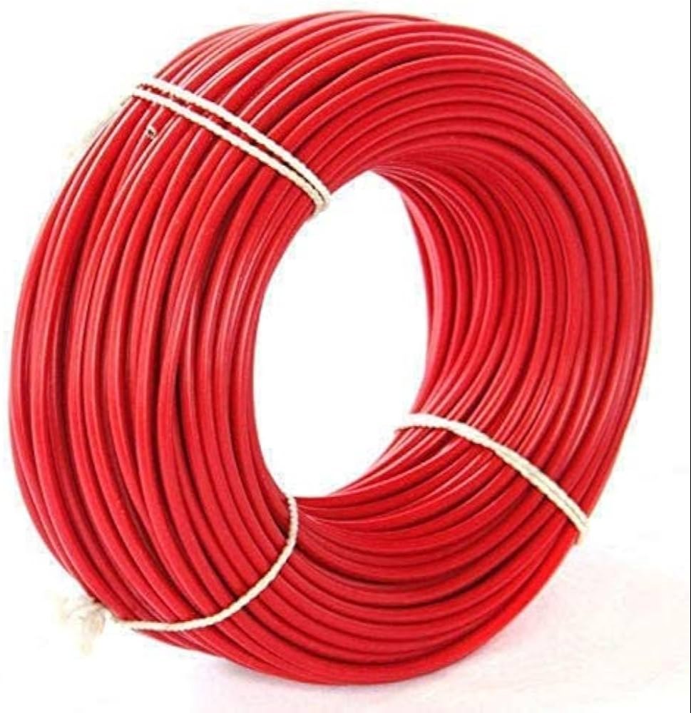
Basic System Functional Operation: In an analogue addressable system detectors are wired in a loop around the building with each detector having its own unique 'address'. The system may contain one or more loops depending upon the size of the system and design requirements. The Fire Control Panel 'communicates' with each detector individually and receives a status report e.g. Healthy, In Alarm or In Fault etc. As each detector has an individual 'address' the fire alarm control panel is able to display/indicate the precise location of the device in question, which obviously helps speed the location of an incident. Sounders may either be conventionally wired or by using addressable sounders, wired upon the "loop" thereby making considerable savings in terms of cable and labour
A Fire Alarm Control Panel (FACP) / Fire Alarm Control Unit (FACU), is an electric panel that is the controlling component of a fire alarm system which is installed at various places as a protective measure against fire; sounds an alarm when actuated by a fire detection system. Fire Alarm System is essential to warn all occupants that a fire or emergency situation exists. Sometimes fire detection and alarm systems are used to compensate or to give special cover for items of high value. In case of fire early detection of smoke and heat helps in fighting the fire effectively & extinguishing it in nascent stage. Thus by early detection, we can prevent the fire from spreading in turn saving life and loss of property and business.
Whatever the reason, an automatic fire detection and alarm system generally provides a network of manual call points, fire sensors and alarm warning devices over the area covered. It is, in effect, the eyes and mouth of the building to constantly monitor the building and warn if a fire breaks out, or is suspected in the way we do, if we see flames or smell burning.
Water Spray System is a special fixed pipe system connected to a reliable source of pressurised water supply and equipped with water spray nozzles for application on area / equipment to be protected. The system can be operated automatically by connection to an automatic detection and alarm system or manually, or both.
Water spray systems are generally used for fire protection of flammable liquid and gas storage tanks, piping, pumping equipment, electrical equipment such as transformers, oil switches, rotating electrical machinery etc. and for protection of openings in fire walls and floors.
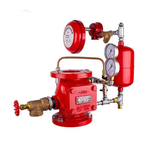
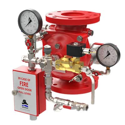
The piping system is connected to the water supply through an automatically actuated Deluge Valve, which initiates flow of water. Automatic actuation is achieved by operation of automatic detecting equipment installed along with water spray nozzles. There are two types of systems namely High Velocity and Medium Velocity systems.
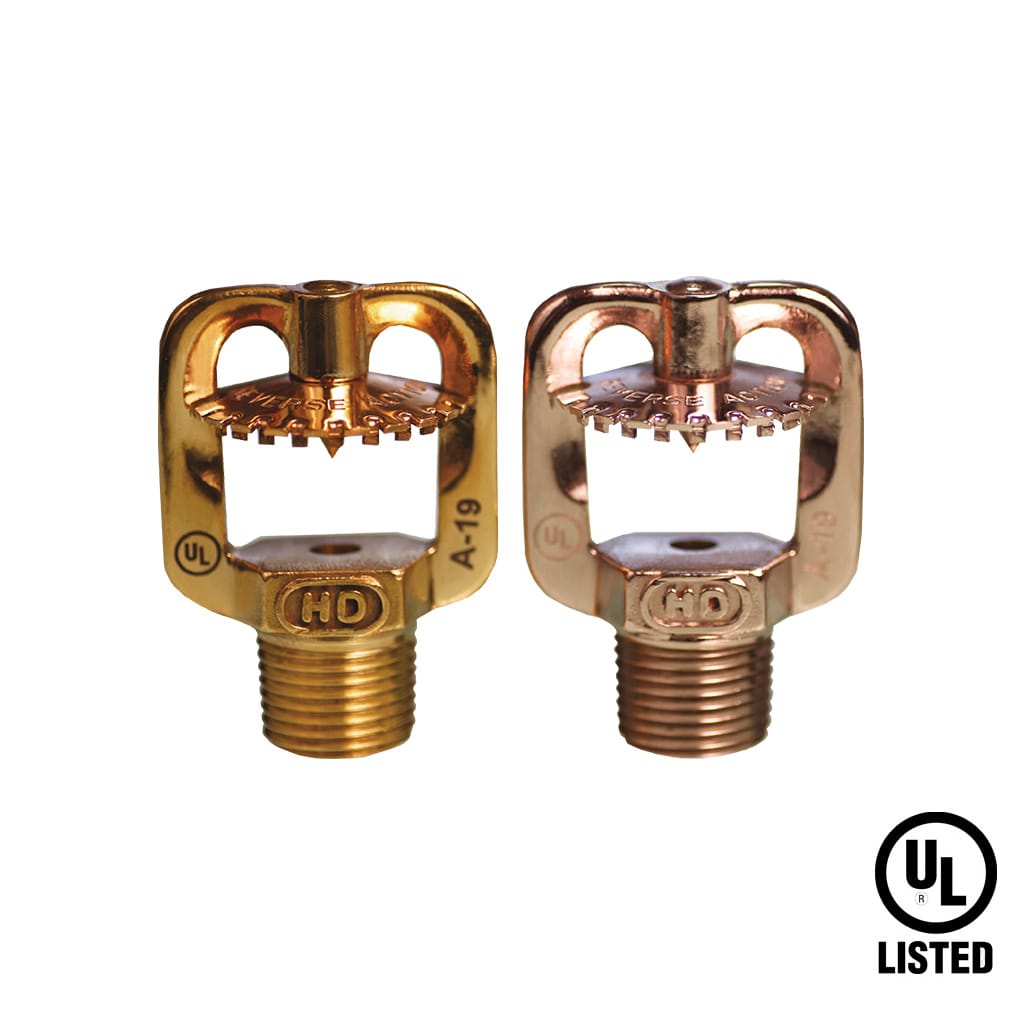
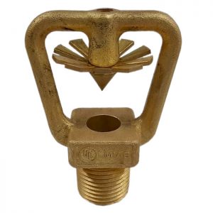
• Medium Velocity Water Spray Systems (MVWSS) are used for fire protection of areas with fire risks from low FP flammable liquids (FP below 65 Degree C) and also for fire extinguishment of water miscible liquids (polar solvents, alcohols etc.) small installation as it becomes cost effective and also serves the purpose of safety and location identification is easy.
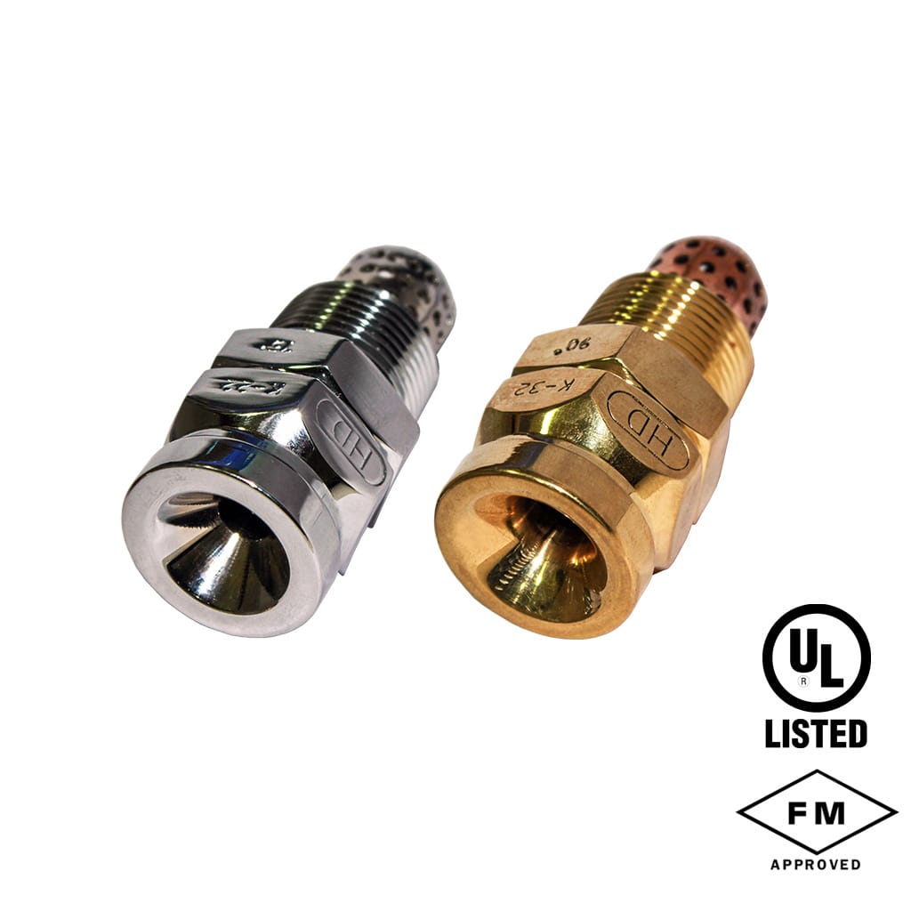
• High Velocity Water Spray Systems (HVWSS) are used for extinction of fires in flammable medium and heavy oils or similar flammable liquids having a flashpoint above 65 Degree C. (E.g. Transformer Fires, Lube Oil Tanks, Etc).
The high / medium velocity water spray system protection operates on the same principle as a deluge system. Deluge Valve is known as a system control valve in a deluge system, used for fast application of water in a spray system. Deluge valve is a quick release, hydraulically operated diaphragm valve. It has three chambers, isolated from each other by the diaphragm operated clapper and seat seal. While in 'SET' position, water pressure is transmitted through an external bypass check valve and restriction orifice from the system supply side to the top chamber, so that supply pressure in the top chamber acts across the diaphragm operated clapper which holds the seat against the inlet supply pressure because of differential pressure design. On detection of fire the top chamber is vented to atmosphere through the outlet port via opened actuation device(s). The top chamber pressure cannot be replenished through the restricted inlet port, thus it reaches less than half the supply pressure instantaneously and the upward force of the supply pressure lifts the clapper allowing water to enter the system piping network and alarm devices. This allows the water to flow out through the projectors in the form of high / medium velocity water spray and extinguishes the fire. Generally, a water motor operated gong (as in the case of sprinkler systems) sounds the fire alarm. Sometimes, additionally an electrical alarm may also be provided. The water spray systems should have isolation facilities so as to enable periodic testing, maintenance etc. Normally, all cut-off valves should be locked open.
We offer best Design & Engineering of an integrated HVW / MVW spray system as per national/ international standard and guidelines. Our designed system in accordance to international standards is an arrangement of Piping, Deluge & Automatic Value, Nozzle, Q.B. Detectors etc. to make an automatic or manually actuated fixed pipe system connected to a water supply to provide a specific water discharge and distribution over the protected surface of area.
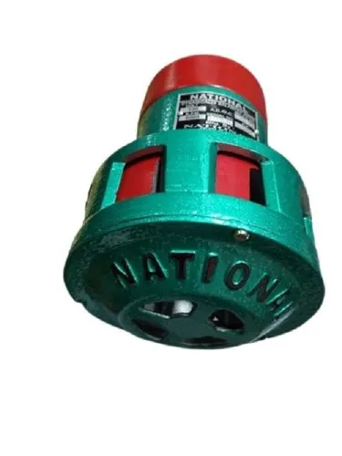
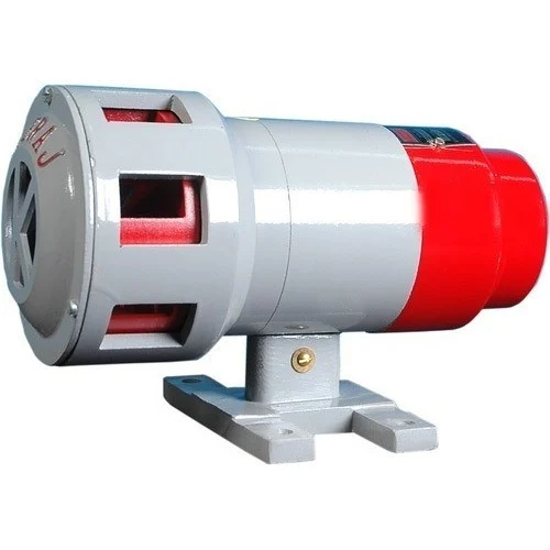
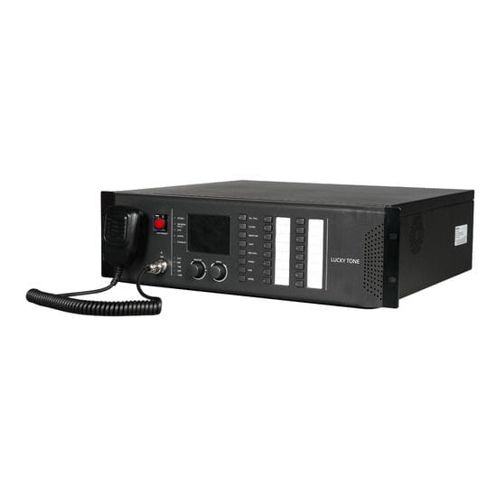
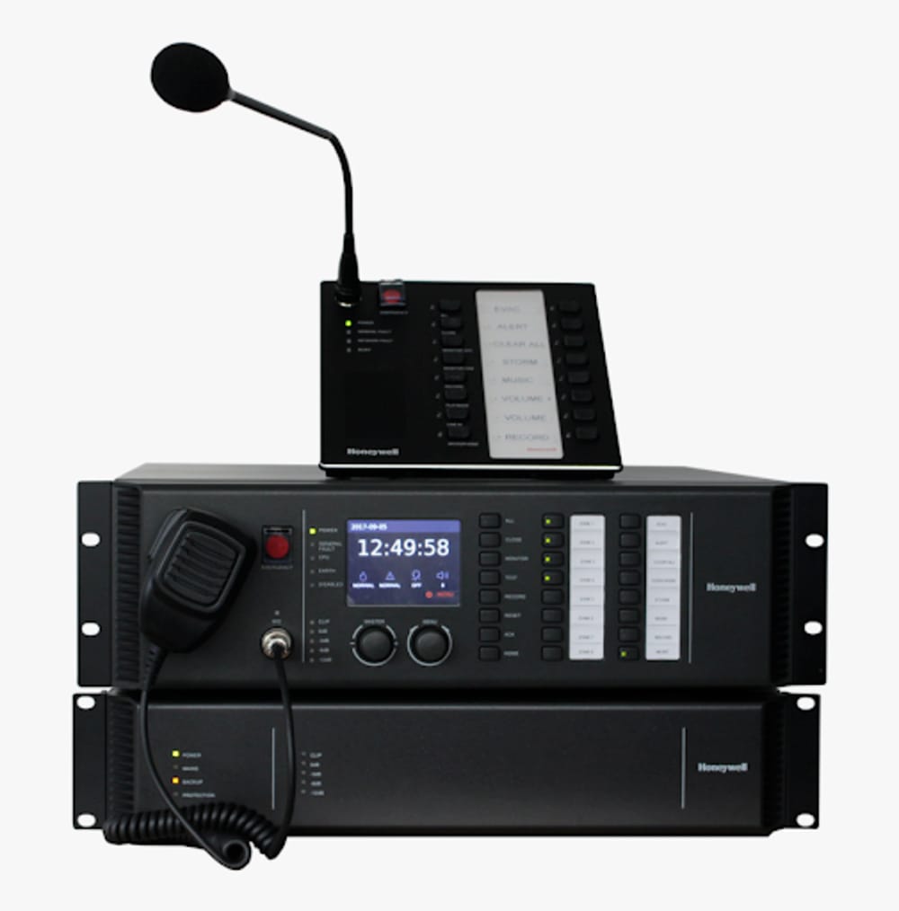
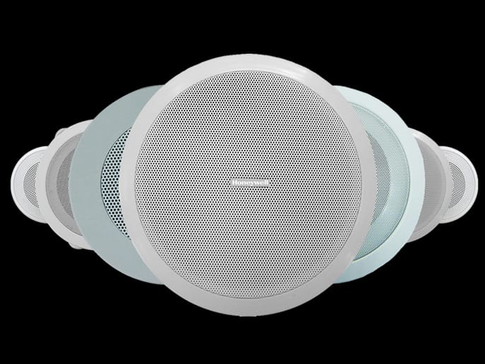
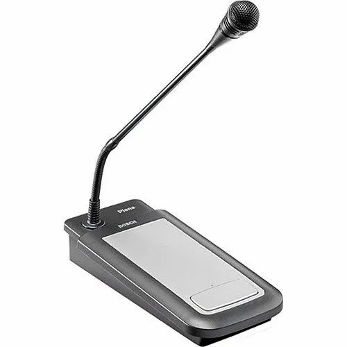
A public address system (PA system) is an electronic sound amplification and distribution system with a microphone, amplifier and loudspeakers, used to allow a person to address a large public, for example for announcements of movements at large and noisy air and rail terminals. Simple PA systems are often used in small venues such as school auditoriums, churches, and small bars. PA systems with many speakers are widely used to make announcements in public, institutional and commercial buildings and locations. Intercom systems, installed in many buildings, have microphones in many rooms allowing the occupants to respond to announcements.
Public Address (P.A) systems combine the very latest technology in amplifiers, microphones and speakers to bring this ideal audio environment to modern public spaces.
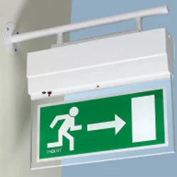
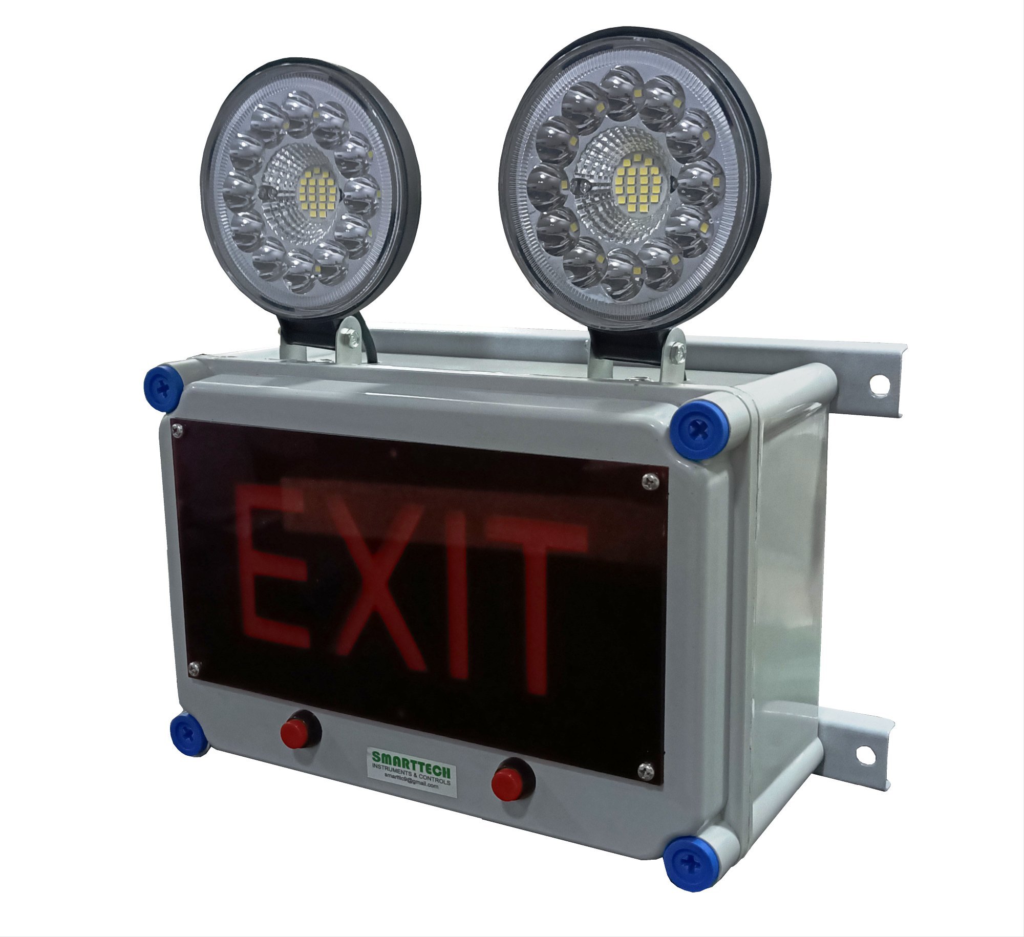
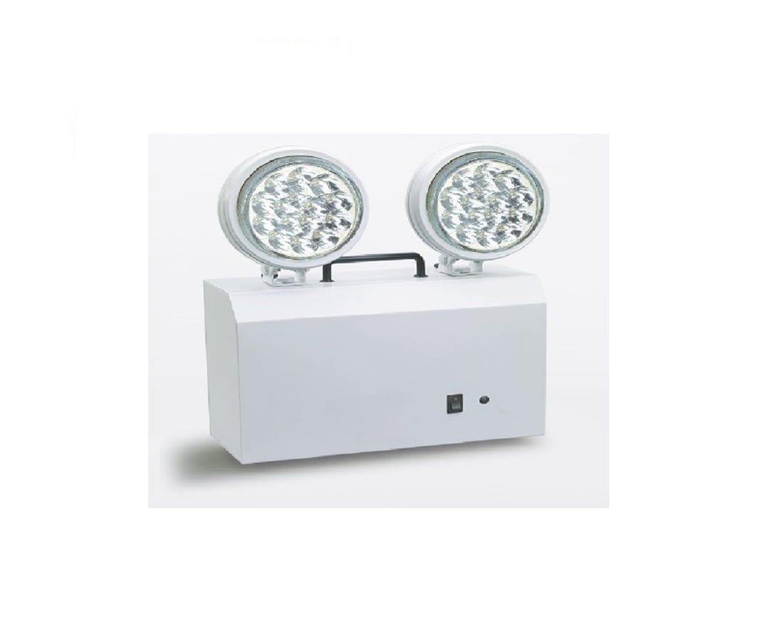
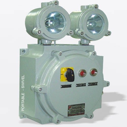
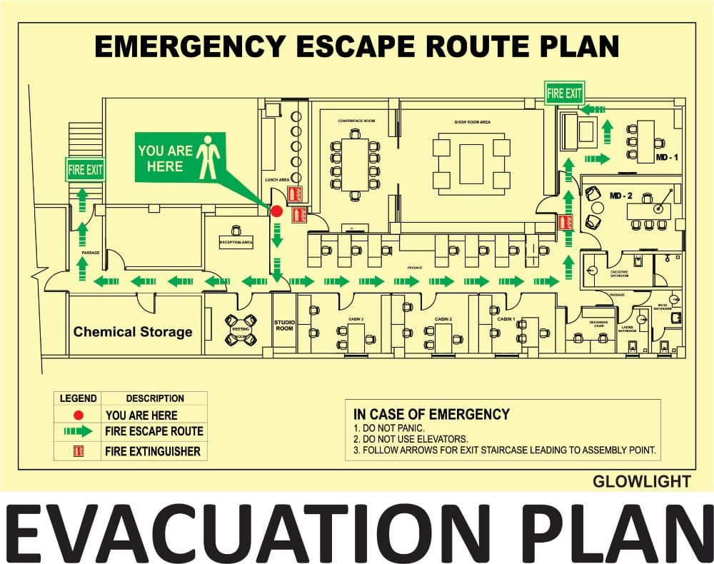
An emergency lighting system is designed to create personal safety and allow the safe evacuation of the building. An emergency lighting system must work faultlessly in all situations which is why high demands are made on reliability. The system is a safety element and must be well designed and planned. The design of emergency lighting systems are specified in the standards BS 5266 Parts 1 & 7 and EN 1838 Demands are made in the standards for different environments and application areas. Examples of different environments where demands vary are: escape routes, anti-panic lighting and lighting of high risk areas. The emergency lighting system usually consists of a combination of safety signs and general luminaires equipped with an emergency lighting function. An emergency lighting system can be either centralised or decentralised, i.e. with a central power supply or with an integrated emergency lighting solution direct in the luminaire.
Emergency lighting is a vital and effective life safety tool, providing reassurance and guidance to people at critical times when they need to escape quickly and safely from a building. Specific requirements for emergency lighting are set out in law, and international standards.
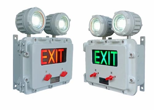
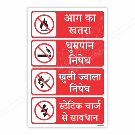
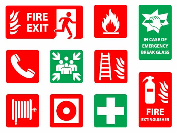
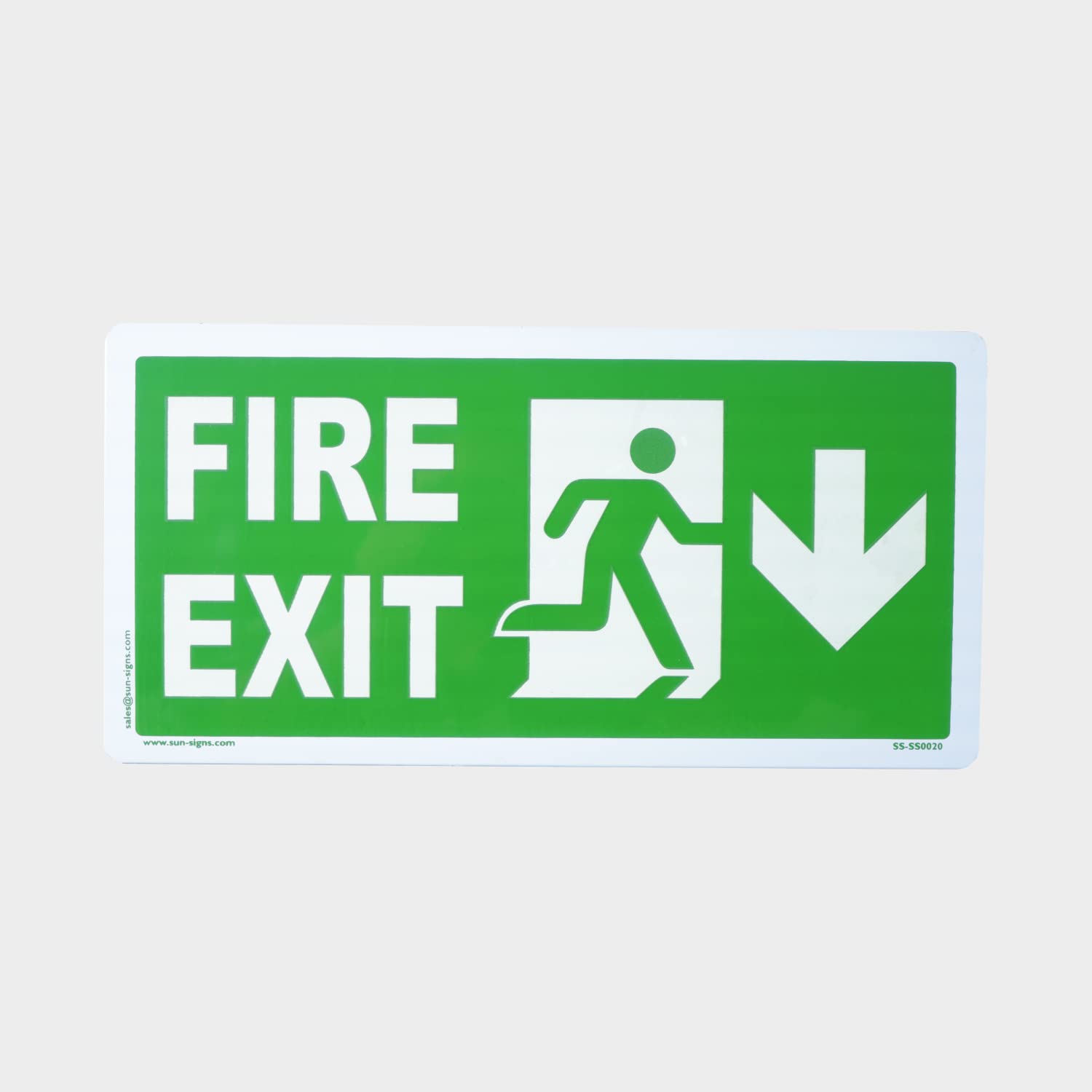
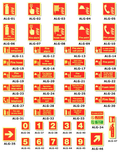
Signage, refers to the design or use of signs and symbols to communicate a message to a specific group, usually for the purpose of marketing. Signs are any kind of visual graphics created to display information to a particular audience. This is typically manifested in the form of way finding information in places such as streets or on the inside and outside of buildings. Signs vary in form and size based on location and intent, from more expansive banners, billboards, and murals, to smaller street signs, sandwich boards and lawn signs. Newer signs may also use digital or electronic displays.

Introduction In a high-rise building, the stairs typically represent the sole means of egress during a fire. It is imperative for the exit stairs to be free of smoke and to incorporate design features that improve the speed of occupant egress. Most building codes require the fire stairwells in a high-rise building to be pressurized to keep smoke out.
The stairwell pressurization serves several purposes:
• Inhibit migration of smoke to stairwells, areas of refuge, elevator shafts, or similar areas.
• Maintain a tenable environment in areas of refuge and means of egress during the time required for evacuation.
• Facilitate the fire and rescue operation by improving visibility in the building for the firefighting crew.
• Protect life and reduce damage to property. The International Building Code (IBC) enforced much throughout the United States, recognizes three specific means for providing smoke proof enclosures:
1. Naturally ventilated stair balconies
2. Mechanical ventilation of a stair Stairwell Pressurization Systems
3. Stair pressurization
Due to the relative cost of the associated mechanical systems, and architectural space issues related to providing exterior balconies and stair vestibules, the stair pressurization system is the most widely selected design option. This course discusses the smoke control systems and examines the design considerations associated with stairwell pressurization systems.
Pressurization Method
Pressurization systems use mechanical fans to produce a positive pressure on the stairwells.
The two key pressurization principles are maintaining:
1. A pressure difference across a barrier
2. Average velocity of sufficient magnitude.
Consider an example of a stairwell “A” maintained at a positive pressure relative to lift lobby “B” which is at a higher pressure relative to the fire zone corridor space “C”. Each of the three zones A, B and C are separated by the partition barriers and the doors. The lobby and stairwell (marked green) can be classified as escape routes, refuge area and tenable environment. These invariably repeat themselves at the same position at each floor level for at least a number of successive floors. We learned that air flows from the higher pressure area to the lower pressure area. The principle of maintaining a tenable environment is to prevent migration of smoke laden air from zone “C” to zone “B” and to zone “A”. This is achieved by pressurizing Stairwell Pressurization Systems A. 20 the stairwell and lobby such that the pressure in zone A is greater than the pressure in zone B, which in turn is maintained greater than zone C. Two scenarios exist:
1. Door closed - When the lobby doors are closed, an overpressure of the elevator lobby with respect to the building will prevent smoke infiltration from the building spaces into the lobby. An excess pressure must be maintained in zones A and B so that flow is always outwards, preventing the entry of smoke from zone C. Caution - The pressure should not be so high that it prevents the door opening. A right balance of minimum and maximum pressure difference must be maintained.
2. Door open - When the doors are opened during evacuation, the gaps get much wider and the pressure tends to equalize between two zones. A good pressurization system design must maintain minimum pressures and respond quickly to stair door openings. Studies indicate that the smoke tends to be held back by the outflow of air if the egress velocity from pressurized spaces is sufficiently high. An egress velocity of 200 fpm (~1 m/s) is recommended
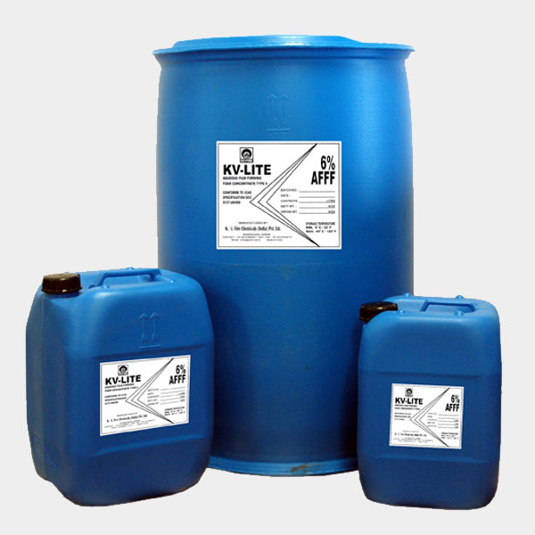
Firefighting foam is a foam used for fire suppression. Its role is to cool the fire and to coat the fuel, preventing its contact with oxygen, thus achieving suppression of the combustion. Firefighting foam was invented by the Moldovan engineer and chemist Aleksandr Loran in 1902.
The surfactants used must produce foam in concentrations of less than 1%. Other components of fire-retardant foams are organic solvents (e.g., trimethyl-trimethylene glycol and hexylene glycol), foam stabilizers (e.g., lauryl alcohol), and corrosion inhibitors.
• Low-expansion foams, such as aqueous film forming foams (AFFFs), have an expansion ratio of less than 20, are low-viscosity, mobile, and can quickly cover large areas.
• Medium-expansion foams have an expansion ratio of 20–200.
• High-expansion foams have an expansion ratio over 200–1000 and are suitable for enclosed spaces such as hangars, where quick filling is needed.
• Alcohol-resistant foams contain a polymer that forms a protective layer between the burning surface and the foam, preventing foam breakdown by alcohols in the burning fuel. Alcohol-resistant foams are used in fighting fires of fuels containing oxygenates, e.g. methyl tert-butyl ether (MTBE), or fires of liquids based on or containing polar solvents.
Class A foams were developed in the mid-1980s for fighting wildfires. Class A foams lower the surface tension of the water, which assists in the wetting and saturation of Class A foams with water. It penetrates and extinguishes embers at depth. This aids fire suppression and can prevent re-ignition.[3] Favourable experiences led to its acceptance for fighting other types of class A fires, including structure fires.
Class B foams are designed for class B fires—flammable liquids. The use of class A foam on a class B fire may yield unexpected results, as class A foams are not designed to contain the explosive vapours produced by flammable liquids. Class B foams have two major subtypes.
Synthetic foams are based on synthetic surfactants. They provide better flow and spreading over the surface of hydrocarbon-based liquids, for faster knockdown of flames. They have limited post-fire security and are toxic groundwater contaminants.
• Aqueous film forming foams (AFFF) are water-based and frequently contain hydrocarbon-based surfactants such as sodium alkyl sulfate, and fluorosurfactants, such as fluorotelomers, perfluorooctanoic acid (PFOA), or perfluorooctanesulfonic acid (PFOS).
• Alcohol-resistant aqueous film-forming foams (AR-AFFF) are foams resistant to the action of alcohols and can form a protective film.
• Fluorine-free foams (FFF, also called F3) are mostly based on hydrocarbon surfactants and are free of any fluorosurfactant.
Protein foams contain natural proteins as the foaming agents. Unlike synthetic foams, protein foams are bio-degradable. They flow and spread slower, but provide a foam blanket that is more heat-resistant and more durable.
Protein foams include regular protein foam (P), fluoroprotein foam (FP) (a mixture of protein foam and fluorinated surfactants), film-forming fluoroprotein (FFFP) alcohol-resistant fluoroprotein foam (AR-FP), and alcohol-resistant film-forming fluoroprotein (AR-FFFP).
Every type of foam has its application. High-expansion foams are used when an enclosed space, such as a basement or hangar, must be quickly filled. Low-expansion foams are used on burning spills. AFFF is the best for spills of jet fuels, FFFP is better for cases where the burning fuel can form deeper pools, and AR-AFFF is suitable for burning alcohols. High-performing FFF are viable alternatives to AFFF and AFFF-AR for various applications. The most flexibility is achieved by AR-AFFF or AR-FFFP. AR-AFFF must be used in areas where gasoline is blended with oxygenates, since the alcohols prevent the formation of the film between the FFFP foam and the gasoline, breaking down the foam, and rendering the FFFP foam virtually useless.
There are 2 main application techniques of applying foam onto a fire, recognized by the European (EN1568) and international (ISO7203) standards:
Sweep (roll-on) method - Use only on a pool of flammable product on open ground. Direct the foam stream onto the ground in front of the product involved. May need to move the hose line or use multiple lines to cover the material. If multiple lines are used, be aware of other firefighters in the area.
Bankshot (bankdown) method - Firefighter uses an object to deflect the foam stream so it flows down the burning surface. Application should be as gentle as possible. Direct the foam at a vertical object. Allow the foam to spread over the material and form a foam blanket.
Raindown method - Used when unable to employ the bankshot method or the roll-on method. Loft the foam stream into the air above the material and let it fall gently onto the surface. Effective as long as the foam stream completely covers the material. Might not be effective if wind conditions are unfavorable
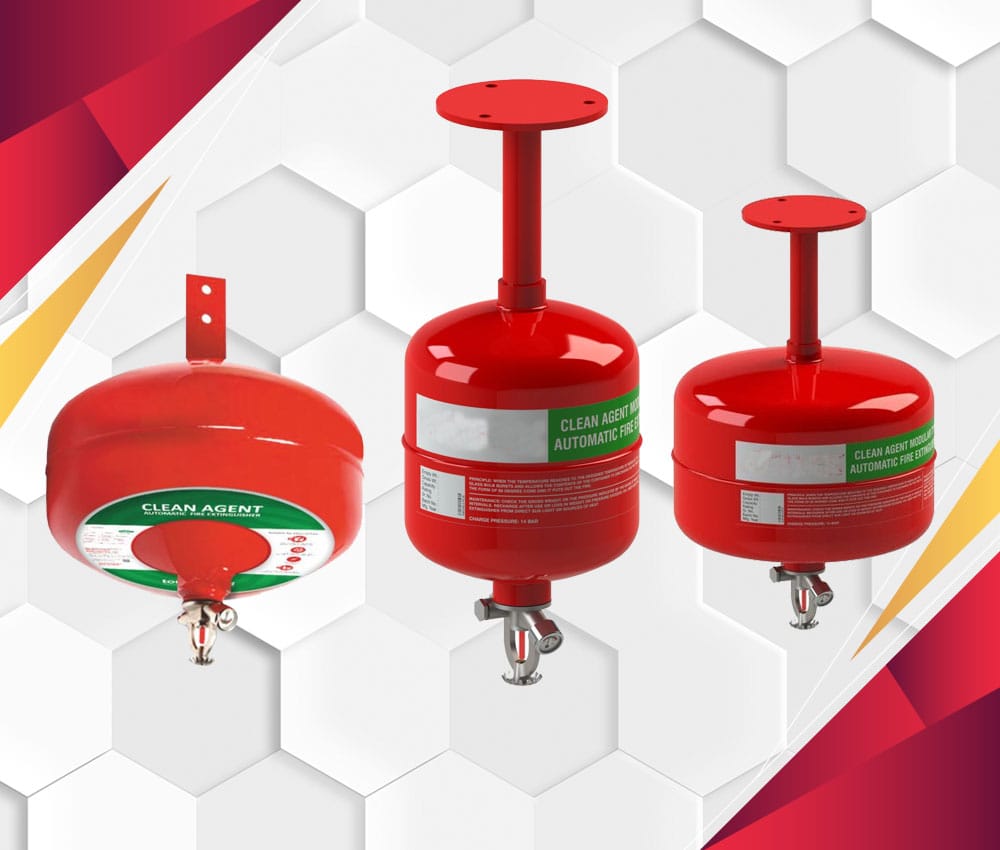
Gaseous fire suppression, also called clean agent fire suppression, is the use of inert gases and chemical agents to extinguish a fire. These agents are governed by the National Fire Protection Association (NFPA) Standard for Clean Agent Fire Extinguishing Systems – NFPA 2001 in the US, with different standards and regulations elsewhere. The system typically consists of the agent, agent storage containers, agent release valves, fire detectors, fire detection system (wiring control panel, actuation signaling), agent delivery piping, and agent dispersion nozzles.
There are four means used by the agents to extinguish a fire,
• Reduction or isolation of fuel. No agents currently use this as the primary means of fire suppression.
• Reduction of heat. Representative agents: Clean agent
• Reduction or isolation of oxygen: Representative agents: IG-01 (argon); Argonite / IG-55 (ProInert) (a blend of 50% argon, 50% nitrogen); CO2, carbon dioxide; Inert Gas 541 IG-541 Inergen (a blend of 52% nitrogen, 40% argon, and 8% CO2); and IG-100 (NN100), nitrogen.
• Inhibiting the chain reaction of the above components.
Broadly speaking, there are two methods for applying an extinguishing agent: total flooding and local application:
• Systems working on a total flooding principle apply an extinguishing agent to a room in order to achieve a concentration of the agent (volume percent of the agent in air) adequate to extinguish the fire. These types of systems may be operated automatically by detection and related controls or manually by the operation of a system actuator.
• Systems working on a local application principle apply an extinguishing agent directly onto a fire (usually a two dimensional area), or into the three dimensional region immediately surrounding the substance or object on fire. The main difference in local application from total flooding design is the absence of physical barriers enclosing the fire space.
In the context of automatic extinguishing systems, local application generally refers to the use of systems that have been emplaced some time prior to their usage rather than the use of manually operated wheeled or portable fire extinguishers, although the nature of the agent delivery is similar and many automatic systems may also be activated manually. The lines are blurred somewhat with portable automatic extinguishing systems, although these are not common
Room integrity testing (RIT) is also required in conjunction with gas fire suppression systems. RIT ensures that in the event of a fire, the room's containment is sufficient to ensure the effectiveness of the suppression system. RIT works by creating pressure within the room or enclosure where the suppression system has been installed and ensuring that the gas does not escape from the room so quickly that it is unable to extinguish the fire.
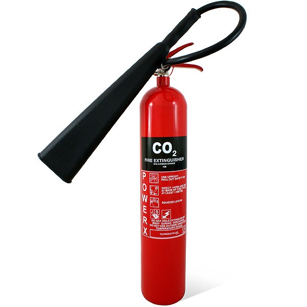
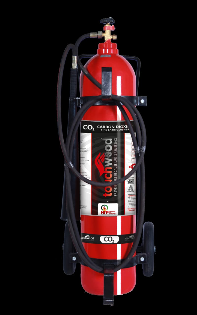
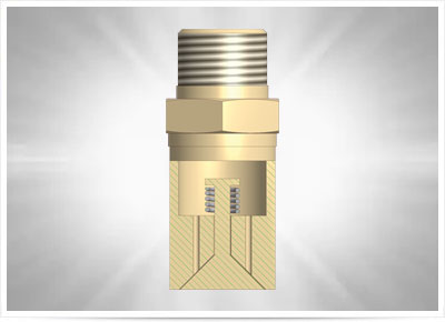
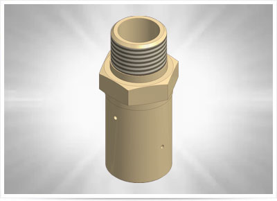
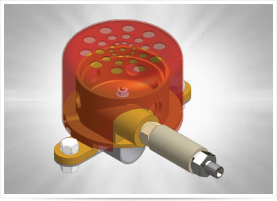
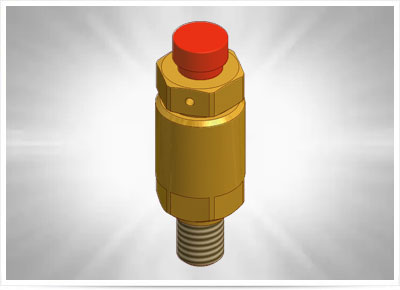
Under normal atmospheric temperature and pressures, carbon dioxide exists as a colourless, odourless gas which is about 1.5 times heavier than air. Carbon dioxide will not burn or support combustion and will not sustain life. When confined within a suitable pressure vessel and depending on temperature and pressure conditions, carbon dioxide can exist in any of the three stages of matter viz solid, liquid and gas
High pressure CO2 system is a specialized fire extinguishing system designed to store carbon dioxide at a pressure of 850psig (at 21˚ C) in high strength alloy steel cylinders. The cylinders contain the CO2 required to protect the largest single hazard. On large hazards where several cylinders are required, a manifold is used and several cylinders are connected to manifold by means of hoses and valves. Cylinder valves control the CO2 flow to the hazard through properly sized pipe, terminating in nozzles that apply the CO2. Flow rate is controlled by nozzle orifices as well as pipe sizes. The cylinder master valves are electronically operated and the slave valves are pressure actuated. The master valves can be automatically and/or manually operated. CO2 fire suppression systems work very well in places where conventional fire suppression techniques might not be practical.
• Paint and varnish manufacturing and processing areas.
• Powder coating and Painting booths.
• Transformers and substations.
• Rolling mills and Turbines.
• False Floors and cable shafts.
• Engine test benches and SHIP Engine Room / compartments.
• Printing machines.
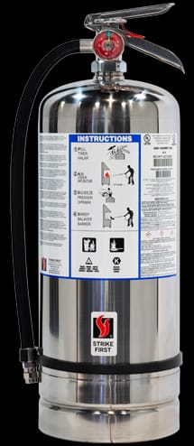
Risk of fire hazard proves to be very dangerous in the modern commercial kitchen. Fire in kitchen is generally due to burning of oil. Oil & fats burn at relatively high temperature and hence once they catch fire, extinguishing them is very difficult. Open flames, red hot cooking surfaces and a heavily grease- laden environment help the kitchen fire to spread quickly and have proven to be very difficult to extinguish. With the aim to protect modern kitchens from such risks we have developed KITCHEN FIRE SUPPRESSION SYSTEM. The system is developed according to the NFPA & UL Standards. It can be widely used in the Kitchens of the Hotels, Institutes, Restaurants and Hospitals etc.
• The system consists of wet agent tank, Heat sensing cable, Nozzles, and Piping.
• Optional (Temperature Sensor)
• The system consists of automatic as well as manual actuation.
• On actuation, system starts spraying Synergy low PH – liquid fire suppressant on plenum area, cooking surface, exhaust duct system with predetermined flow rate.
• On contact with hot grease, it forms a layer of soap like foam on the surface, acting as an insulation between hot grease and atmosphere, thus cutting down Oxygen Supply.
• The system is capable of shutting down other appliances on system actuation, if required.
• Additional equipments such as gas shutoff valves, alarm, warning lights etc. can be integrated with the system.